
Meraki Network Redundancy: From a Basic Cloud-Managed Network to High Availability
By Gary Asher | The Lauer IT Group
Cisco Meraki makes firewalls, switching, wireless, monitoring, and multi-site management easier to operate from a common cloud dashboard. That simplicity is valuable, but cloud management should not be confused with automatic network redundancy.
A site can have a Meraki MX security appliance, an MS switch, and several MR access points and still have single points of failure in its carrier, firewall, switching, power, cabling, DHCP, DNS, or voice design.
Quick Summary: Meraki redundancy is built in layers. Dual WAN protects against a carrier failure. An MX warm-spare pair protects against an MX failure. Redundant switching protects the default gateway and access layer. Multiple access points protect wireless coverage. Independent power, diverse cabling, working DHCP and DNS, and tested voice recovery protect the complete service chain.
How to Read This Article: This is a design study based on current Cisco Meraki documentation and practical network-resilience principles. It does not claim that every configuration described has already been deployed by The Lauer IT Group. Documented Meraki capabilities, design recommendations, and items requiring pilot or laboratory validation are identified separately.
What the Meraki Cloud Does—and Does Not Do
Meraki uses an out-of-band cloud-management architecture. Normal client data does not travel through the Meraki cloud. If a device temporarily loses contact with the dashboard, most local traffic can continue using the last safe configuration.
- Local users can continue reaching printers, file shares, and other local resources.
- Internet access can continue when the WAN path remains available.
- Firewall and quality-of-service policies continue to be enforced.
- DHCP leases can be issued and renewed.
- Wireless clients can continue roaming between access points.
- Established VPN tunnels can continue operating.
During a cloud-connectivity interruption, administrators may temporarily lose dashboard configuration, monitoring, diagnostics, and cloud-hosted functions such as certain splash-page services. A cloud-managed network therefore still needs local documentation, secure credentials, outage procedures, and a way to diagnose power, carrier, addressing, and physical-layer problems.
Meraki reference: Behavior During a Connection Loss to the Cisco Meraki Cloud.
Level 0 — The Basic Meraki Network
A small Meraki deployment may begin with one fiber circuit, one MX security appliance, one MS switch, and one or more MR access points. Computers and IP phones connect to the switch, while wireless devices connect through the MR access points.
Meraki Level 0 — Fiber Internet → Single MX → Single MS Switch → PCs, IP Phones, and MR Access Point.
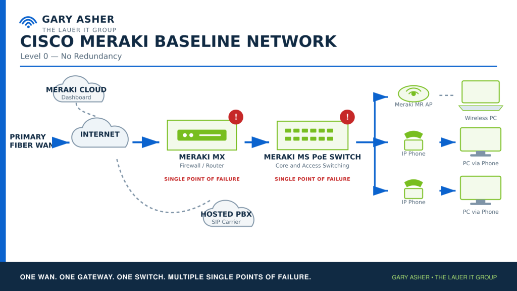
This design is straightforward and may be appropriate where short outages are acceptable. However, it contains several single points of failure:
- One internet carrier and one carrier handoff
- One MX appliance
- One switch and one switch power path
- One uplink between the firewall and switch
- Possibly one access point for an important coverage area
- One UPS, electrical circuit, MDF, or cabling pathway
- DHCP, DNS, domain-controller, SBC, or application services reachable through only one network path
The baseline cost evaluation should include more than the initial purchase. Downtime may create emergency labor, expedited shipping, lost calls, delayed appointments, interrupted imaging workflows, reduced productivity, and damage to customer confidence.
Level 1 — Dual Internet on One MX
The first resilience improvement is normally a second internet connection. Fiber is a strong primary service. A business-class coax circuit or a cellular service can provide a separate recovery path.
Primary Fiber with Coax Backup
Coax is often the best value when it comes from a different carrier and uses a sufficiently independent outside-plant path. It commonly provides more predictable bandwidth than cellular and avoids dependence on radio coverage. However, fiber and coax entering through the same pole, conduit, building entrance, or provider facility may still share risk.
Primary Fiber with Cellular Backup
Cellular can create useful physical diversity because it does not depend on the same last-mile cable. It may be the better choice when coax is unavailable or shares too much infrastructure with fiber. Capacity, signal quality, antenna placement, data plans, carrier congestion, public addressing, inbound services, VPN behavior, and failback must be evaluated.
Depending on the selected MX model and design, cellular may be provided through an integrated cellular MX model, a supported Meraki MG cellular gateway, or another supported handoff to an MX WAN port. Exact support and failover order must be verified for the chosen hardware and firmware. Cisco Meraki documents specific limitations for cellular operation in an MX high-availability pair.
Meraki Level 1 — Fiber on MX WAN 1, Coax or Cellular on the backup WAN path, one MX, one MS switch, MR wireless, PCs, and phones.
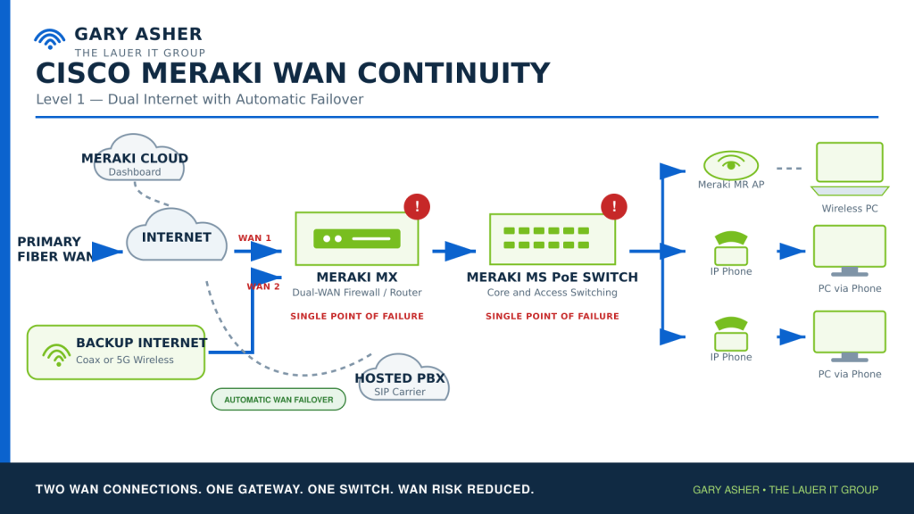
Meraki connection monitoring determines whether an uplink remains usable. The design must test more than link state. DNS resolution, upstream reachability, Auto VPN, non-Meraki VPN, hosted applications, inbound services, NAT, public-IP changes, monitoring, and voice calls should be validated on both circuits.
Meraki references: Configuring Multi-WAN Uplinks on Supported MX Appliances and MX Warm Spare and Cellular Failover Behavior.
Level 2 — Dual WAN with MX High Availability
Dual WAN protects against a carrier failure but leaves the MX itself as a single point of failure. Level 2 adds a second matching MX in an active/passive high-availability pair, traditionally called a warm-spare pair.
- The primary and spare must be the same MX model and compatible regional designation.
- VRRP is used on the LAN side to coordinate the active and passive appliances.
- Connection monitoring participates in detecting loss of usable WAN service.
- DHCP lease information is synchronized between the pair.
- Only one MX license is required for the supported warm-spare pair.
- Alerts can report a warm-spare failover.
Uplink IPs Versus Virtual Uplink IPs
Meraki supports using each MX appliance’s individual uplink addresses or shared virtual uplink IP addresses. Individual uplink addresses require fewer public IPs but can create more disruption because outbound flows change public addresses during failover. Virtual uplink IPs require additional public addresses on the same upstream subnet but can reduce disruption by preserving the public address used by active traffic.
For a virtual IP on an uplink, the primary address, spare address, and virtual address must be unique and reside in the same upstream subnet. Each carrier handoff must be designed so both MX appliances can reach the required WAN broadcast domain.
Avoiding a Dual-Active Condition
The MX appliances exchange VRRP information across configured LAN VLANs. If that communication is interrupted, the spare may believe the primary has failed and become active. A dual-active state can disrupt DHCP, routing, VPNs, and normal client traffic. The LAN design and failover tests must confirm reliable communication between both appliances.
Insert Drawing: Meraki Level 2 — Fiber and Coax or Cellular available to two matching MX appliances in an active/passive pair, connected to redundant downstream switching.
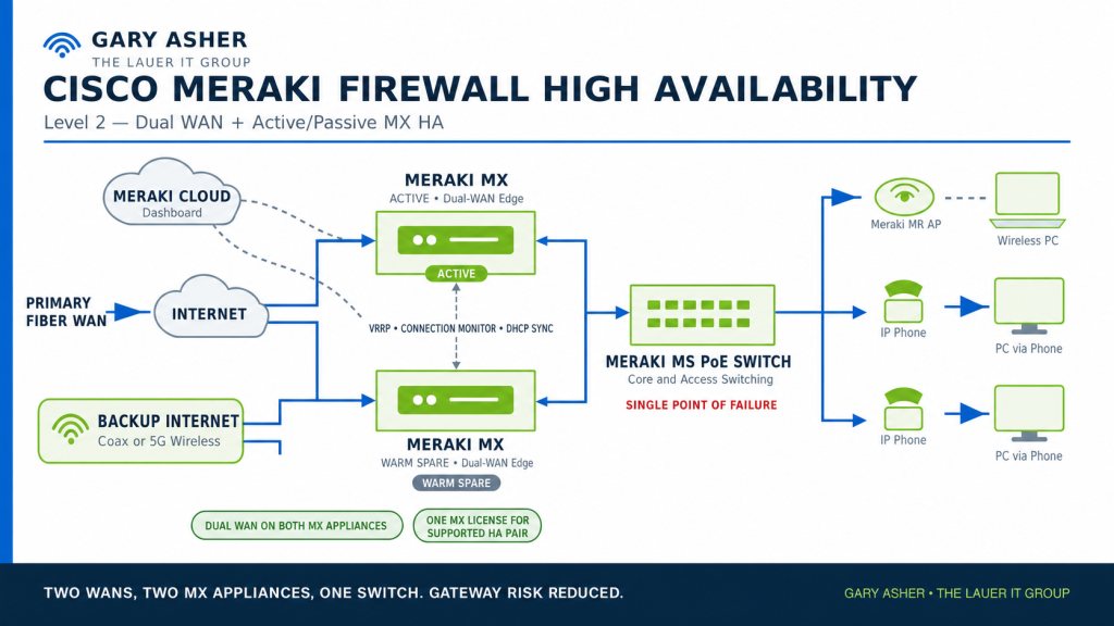
Meraki reference: MX Warm Spare — High-Availability Pair.
Level 3 — Redundant Switching and Wireless
Two MX appliances still depend on the switching infrastructure beneath them. Meraki documentation describes two primary approaches for redundant Layer 3 switching: switch stacking or Layer 3 warm spare using VRRP.
Option A — Supported Switch Stack
Cisco Meraki generally recommends supported switch stacking for Layer 3 resiliency because it can provide faster failover and operational simplicity. Each MX connects to more than one member of the downstream stack, and access points and critical endpoints are distributed across stack members.
- Verify that the exact switch models support the selected physical or flexible stacking design.
- Use redundant stack connections and document the supported topology.
- Distribute MX uplinks, access points, servers, and critical access ports across members.
- Review the impact of software upgrades, stack control, shared configuration, and simultaneous maintenance.
- Provide separate UPS and electrical paths where practical.
Option B — Layer 3 Warm-Spare Switches
Where stacking is unavailable or intentionally avoided, two identical supported Layer 3 switches can use Meraki warm-spare functionality. VRRP provides a consistent default gateway for client VLANs.
- Both switches must be supported Layer 3 models.
- Each switch requires its own valid license.
- The switches need an alternate path for VRRP communication.
- The warm-spare switch receives the primary switch’s Layer 3 interface and routing configuration.
- A switch configured as a warm spare cannot also participate in a switch stack.
- Meraki documentation states that OSPF cannot be enabled when the switch is operating as a warm spare.
This is a major difference from the independent routed-switch design used in the Cisco article. A Meraki Layer 3 warm-spare pair is a VRRP gateway-redundancy design, not two independently routed OSPF cores. The architecture should follow the behavior of the selected Meraki feature rather than force a traditional Cisco design onto the dashboard.
Meraki references: Meraki Campus LAN Planning and Design and MS Warm Spare Overview.
Wireless Continuity
A resilient site should not attach every access point to one switch or power source. At least one appropriately placed MR access point should remain available through each switching path. Coverage overlap, client capacity, channel planning, authentication, VLAN availability, DHCP, DNS, firewall policy, and application reachability must all work after a switch failure.
Meraki’s out-of-band cloud architecture allows wireless traffic and roaming to continue during a temporary dashboard-connectivity interruption, but a failed switch, failed PoE source, missing VLAN, unreachable RADIUS server, or unavailable DHCP service can still prevent users from working.
Insert Drawing: Meraki Level 3 — Dual WAN, two MX appliances, two-switch stack or Layer 3 warm-spare pair, one MR access point on each switch path, PCs, phones, servers, and protected cloud services.
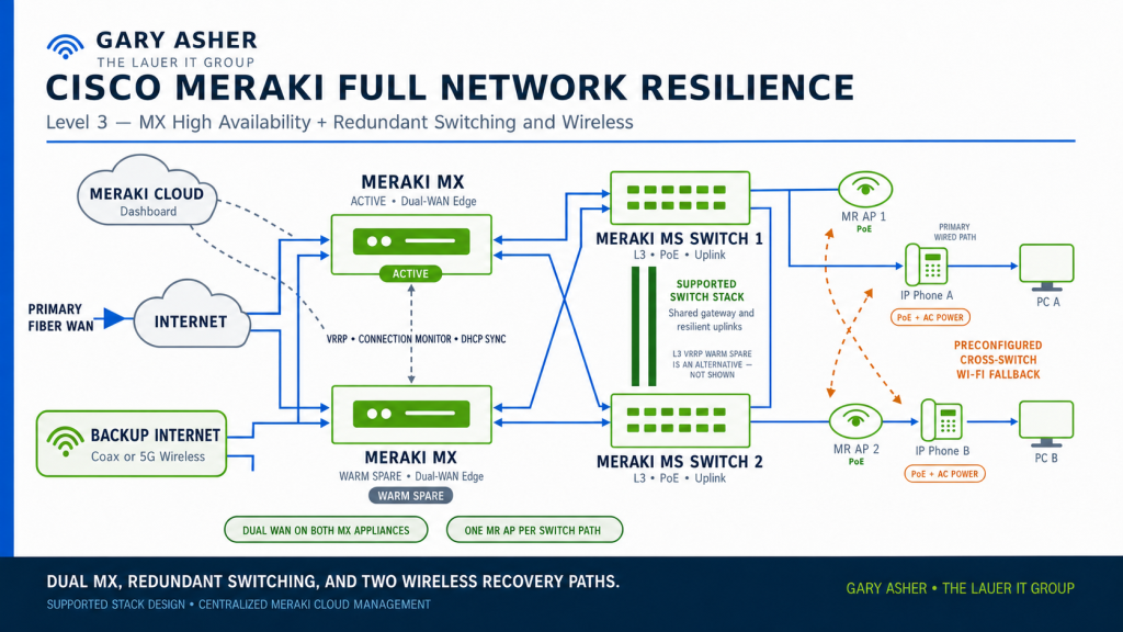
Phones, PCs, and 3CX Continuity
The Meraki infrastructure does not remove the endpoint questions identified in the Cisco design. Phones and computers must still respond correctly when their wired path disappears.
- Wi-Fi-capable phones need approved AC power if they are expected to survive loss of switch PoE.
- Continuity SSIDs and credentials must be configured before an outage.
- Voice and data continuity networks need DHCP, DNS, NTP, routing, firewall policy, and 3CX reachability.
- The protected SBC path must be reachable from all required wired and wireless phone networks.
- Critical PCs should retain an independent wireless recovery path until phone-to-PC Wi-Fi bridging is proven reliable.
- The 3CX desktop and mobile applications provide additional ways to place and receive new calls.
The separate production-phone case study will test the Fanvil X4U, Fanvil X4U-V2, and Yealink T54W. Results will include wired-to-wireless transition, DHCP and VLAN behavior, 3CX registration, SBC behavior where applicable, PC-port pass-through, call testing, recovery time, and automatic return to Ethernet.
DHCP, DNS, Identity, and Application Dependencies
A surviving firewall, switch, or access point is not enough if the service chain behind it has failed. Every recovery network should be reviewed for:
- DHCP server availability, synchronized leases, relay behavior, and scope capacity
- Default gateway and route availability
- Internal and external DNS
- Domain controllers, RADIUS, identity providers, and multifactor authentication
- NTP for phones, authentication, certificates, logging, and network devices
- 3CX PBX, router phone, SBC, provisioning, and tunnel reachability
- VPN, NAT, public addressing, and inbound-service behavior on every WAN
- Cloud applications, medical imaging systems, line-of-business applications, and vendor tunnels
When an MX warm-spare pair provides DHCP, Meraki synchronizes lease information between the primary and spare. If DHCP is provided by a Windows server or another system, the redundancy and routing of that service require separate design and testing.
Power, Cabling, MDFs, and IDFs
Cloud management cannot overcome a failed electrical circuit, overheated closet, damaged fiber bundle, or unplugged carrier handoff. The physical design should include:
- Separate UPS protection for redundant MX and switching paths
- Separate electrical circuits and generator support where justified
- Documented UPS runtime and battery-replacement schedules
- Diverse carrier entrances and cabling routes where available
- Redundant fiber between the MDF and critical IDFs
- Correct optics, patch panels, labeling, and cable testing
- Environmental monitoring for heat, moisture, power, and unauthorized access
- Spare optics, cables, power supplies, injectors, and critical endpoint adapters
- Current rack elevations, port maps, VLANs, IP addressing, circuits, and power diagrams
Licensing, Warranty, Support, and Operating Cost
Meraki’s operational model makes licensing and support part of the network architecture. Licenses and hardware warranties are related to continued operations but are not the same thing.
- Current Meraki organizations may use subscription, co-termination, or qualifying legacy per-device licensing, but licensing models cannot be mixed within one organization.
- New organizations default to co-termination unless a subscription key changes the organization to subscription licensing.
- Each managed switch and access point normally consumes the appropriate licensing entitlement.
- A supported MX warm-spare pair requires only one MX license.
- A Layer 3 switch warm-spare pair requires a valid license for each switch.
- Hardware warranty terms vary by product and should be checked against the selected datasheet and current agreement.
- Standard replacement timing may not meet every recovery objective; enhanced RMA service or an onsite spare may still be justified.
Meraki references: Meraki Licensing, Meraki Licensing FAQs, and Returns, Warranties, and End-of-Life Information.
Budget Line Items
- Primary fiber service
- Backup coax or cellular service and data plan
- Static public addresses or additional addresses required for WAN virtual IPs
- Primary and spare MX appliances
- Switches, power supplies, stacking components, optics, and licenses
- MR access points, licenses, antennas, mounts, and cabling
- UPS equipment, batteries, environmental monitoring, and electrical work
- MDF-to-IDF fiber, pathways, patch panels, testing, and labeling
- Phone AC adapters and approved PC Wi-Fi adapters
- 3CX, SBC, carrier, and voice-related requirements
- Enhanced RMA, onsite spares, managed support, monitoring, and after-hours coverage
- Configuration, migration, documentation, staff training, pilot testing, and periodic failover validation
Practical Ways to Control Cost
- Start with dual WAN when carrier failure is the largest known risk.
- Use business-class coax as the backup when it provides adequate diversity and predictable performance.
- Use cellular where it provides greater physical diversity or faster deployment.
- Take advantage of the single-license requirement for a supported MX warm-spare pair.
- Prioritize redundant switching and wireless coverage for front-desk, scheduling, clinical, management, and voice-critical areas.
- Standardize MX, MS, and MR models across comparable sites to simplify training, spares, templates, and support.
- Compare the cost of enhanced RMA service with keeping a properly documented onsite spare.
- Size equipment for realistic throughput with security services enabled, rather than buying solely from raw interface speed.
- Pilot the design at one representative site before purchasing equipment for every location.
- Schedule testing during planned maintenance instead of discovering failover behavior during an emergency.
Gary’s Practical Note: Meraki can simplify administration, but simplicity does not eliminate engineering. A dashboard cannot correct a shared power circuit, one cable path, an unreachable DHCP server, an expired license, inadequate wireless coverage, or an untested recovery procedure.
Pilot and Validation Plan
Because this article is based on documented capabilities and design analysis, the following items should be validated in a Meraki pilot before being presented as field-proven results:
| Test | Expected Result | Status |
|---|---|---|
| Primary fiber failure | MX moves traffic to coax or cellular and required applications recover | Pilot required |
| Primary MX failure | Spare MX becomes active without a dual-active condition | Pilot required |
| MX failback | Original primary resumes correctly and alerts and logs show the transition | Pilot required |
| Public-IP behavior | Document session impact using individual uplink IPs versus WAN virtual IPs | Design-specific test |
| One switch or stack member fails | Critical wired and wireless users retain a valid gateway and surviving network path | Pilot required |
| Cloud dashboard becomes unreachable | Safe local configuration continues forwarding traffic while management is unavailable | Controlled test |
| MR access point or PoE source fails | Clients use surviving coverage without losing required authentication or VLAN services | Wireless survey and pilot required |
| DHCP or DNS path fails | Redundant services remain reachable through the surviving network | Application test required |
| Phone wired path fails | Selected production phones use the continuity SSID and re-register with 3CX | Three-model lab case study pending |
| PC connected behind a phone | Determine whether Wi-Fi pass-through works reliably on each production phone model | Three-model lab case study pending |
| License and support review | Dashboard organization, renewal dates, warranty, and RMA expectations are documented | Pre-purchase validation |
Record convergence time, packet loss, DHCP time, DNS behavior, VPN recovery, application availability, call registration, two-way audio, DTMF, hold, transfer, voicemail, alerting, event logs, dashboard visibility, manual steps, and failback behavior. Repeat successful tests so that a one-time recovery is not mistaken for dependable operation.
Implementation Checklist
- Document business, clinical, voice, and application recovery priorities.
- Confirm the selected MX model’s throughput with required security and VPN features enabled.
- Verify dual-WAN, cellular, warm-spare, and virtual-IP support for the exact MX model and firmware.
- Confirm both WAN services can be delivered appropriately to both MX appliances.
- Select individual uplink IPs or virtual uplink IPs and document the session-impact tradeoff.
- Select a supported switch stack or Layer 3 warm-spare design.
- Verify switch model compatibility, licensing, optics, stacking, VRRP, and routing limitations.
- Distribute access points, critical endpoints, servers, and uplinks across redundant paths.
- Complete a wireless survey for normal operation and the loss of either switching path.
- Validate DHCP, DNS, NTP, identity, VPN, cloud, voice, and business-application dependencies.
- Make the protected 3CX SBC path reachable from every required voice network.
- Install and test approved phone AC adapters and PC Wi-Fi recovery where justified.
- Configure dashboard administrators with least privilege and multifactor authentication.
- Store credentials, recovery codes, license information, configuration records, support contacts, and carrier details in an approved secure credential vault.
- Configure alerts for WAN problems, unreachable devices, and warm-spare failover.
- Record serial numbers, warranties, renewal dates, RMA coverage, and spare-equipment locations.
- Publish staff and technical-support outage procedures.
- Schedule recurring failover tests and update the article when pilot results are available.
Final Thoughts
A resilient Meraki network is not simply a collection of cloud-managed products. It is a coordinated design covering carriers, MX appliances, switching, wireless, phones, computers, licensing, support, power, cabling, DHCP, DNS, identity, applications, monitoring, documentation, and testing.
The practical advantage of Meraki is centralized visibility and a consistent operational model. The engineering responsibility remains the same: understand what each layer protects, identify what can still fail, and prove that the surviving path supports the work the business actually needs to perform.
This article will be updated as the design is reviewed with experienced Meraki administrators and tested in an appropriate pilot environment. The next article will apply the same framework to UniFi, including its different approaches to gateways, switching, wireless, licensing, support, cost, and operational control.